Getting started with the Mongoose OS and ESP32, an easy tutorial
This year, my goal is to learn as much as I can about IoT and AWS, they go well together and a $10 ESP32 board and a few dollars on the AWS account is a great way to get started.

I’ve spent a few weeknights playing around with Mongoose, most of my time was lost searching for documentation and guides, there’s not a lot out there so hopefully if you’re reading this, it’ll save you some time/pain.
Getting setup with Mongoose OS
You can use the Arduino IDE, but I’m going to jump straight in and use Mongoose instead, have a look at the Mongoose site for reasons why it’s a good choice.
Download and install the MOS tool (check their site for latest instructions). Once it’s installed, from the command line run the following to confirm it’s installed OK.
mos --version

The Mongoose OS command line tool
Version: 1.23
Build ID: 20171229-152500/1.23@2bfb56d3+
Update channel: release
If you run mos ui from the terminal you’ll get a browser window open where you can flash/code/view your ESP, I always prefer a CLI if there is one so I’ll skip over the UI stuff here.
In terms of IDE, the best I’ve found so far is Visual Studio Code, it’s free, and is pretty simple to use. Make sure you install the following plugins:
- C/C++
- C++ Intellisense
- Mongoose OS IDE
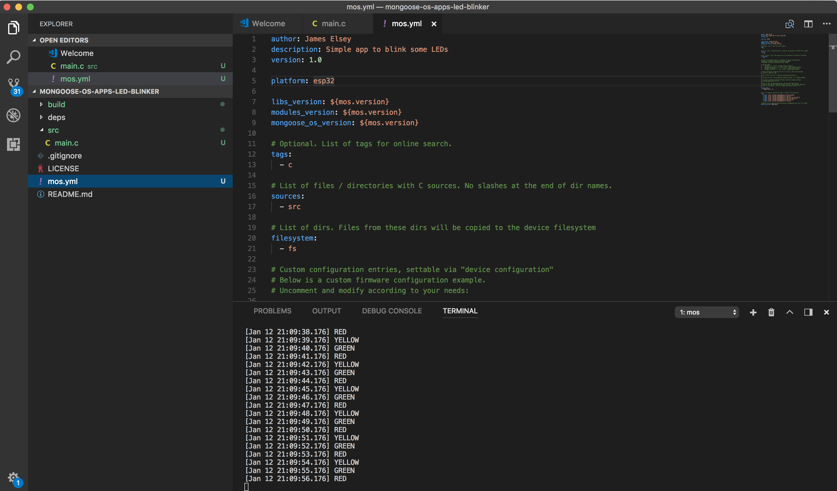
You can also open a terminal, I’ve got mine setup like this, works well for me so far.

Make sure you go into the settings for VS Code and change the save mode, I’ve been caught several times wondering why my code isn’t working, only to realise it doesn’t auto save by default and I’d just been deploying the old code over and over again!
"files.autoSave": "onFocusChange",
Deploying a hello world app
Now we’ve got our environment setup, lets deploy an app. I’ve created a skeleton hello world app so grab that using
git clone https://github.com/jameselsey/mongoose-os-apps-hello-world.git
cd mongoose-os-apps-hello-world
Now build and deploy it using the following:
- mos build – Builds the application, brings in dependencies specified in mos.yml, creates artefact
- mos flash – deploys the artefact to the device and restarts it
- mos console – attaches a console to the device so you can see any output
Check the github, but notice in the code I’ve setup a loop to keep printing hello world, this demonstrates importing some libraries and using a callback. Also notice that there is a newline on the end of the print, I found that if you don’t do this, the print buffers output, so the app will appear like it’s doing nothing for around 5 seconds then you’ll get one line printed with Hello World 50 odd times. The newline forces the buffer to flush to console.
#include <stdio.h>

#include "mgos_app.h"
#include "mgos_timers.h"

static void timer_cb(void *arg) {
  // don't forget the \n to flush print buffer
  printf("Hello world!\n");
  (void) arg;
}

// Entry point to app
enum mgos_app_init_result mgos_app_init(void) {

  // Repeat the timer_cb every 1 second, second argument is boolean to repeat (1 == true)
  mgos_set_timer(1000 , 1 , timer_cb, NULL);

  return MGOS_APP_INIT_SUCCESS;
}
Get familiar with that, then move onto the next section where we make it more interesting.
Making the app a bit more interesting, adding some LEDs
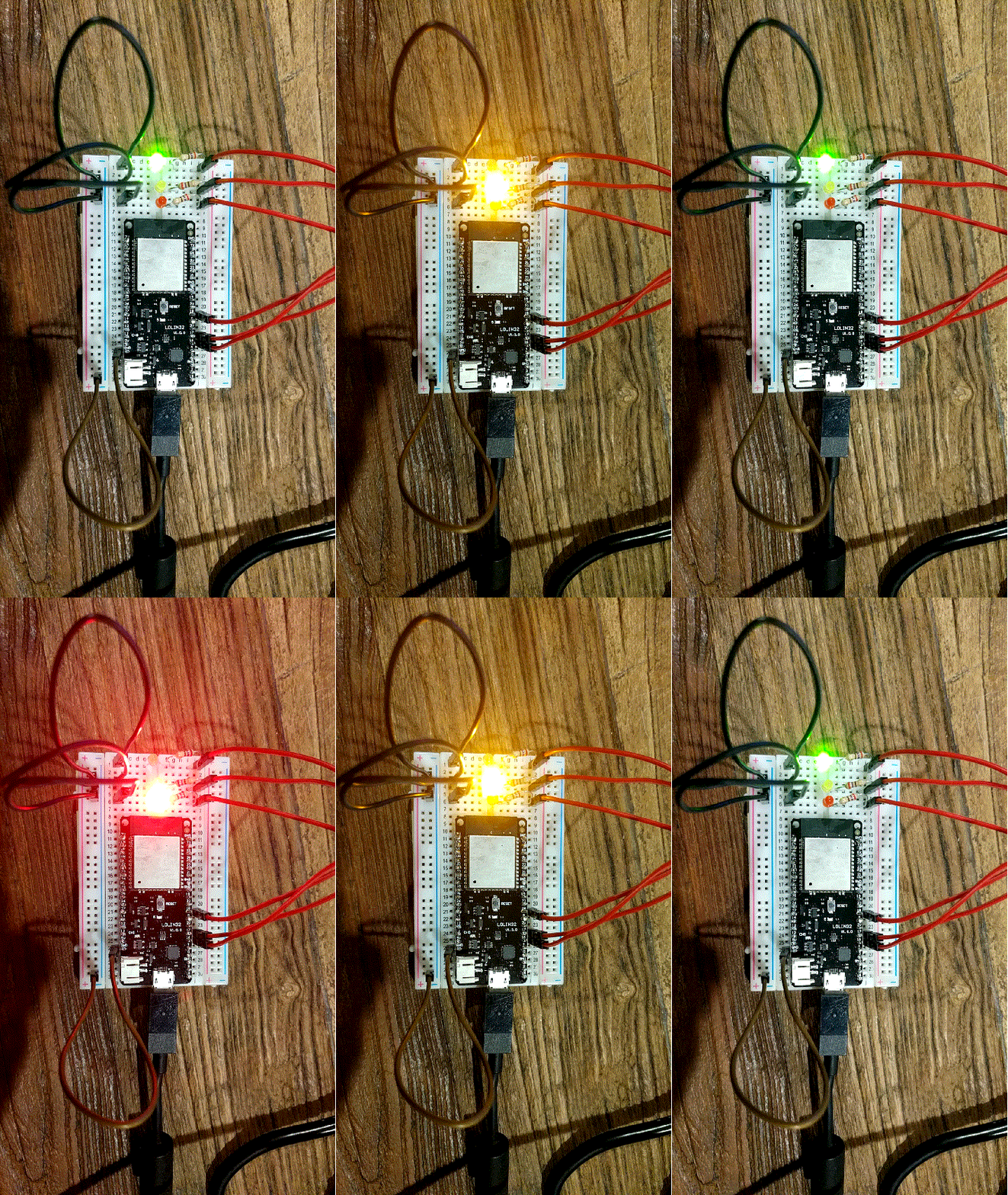
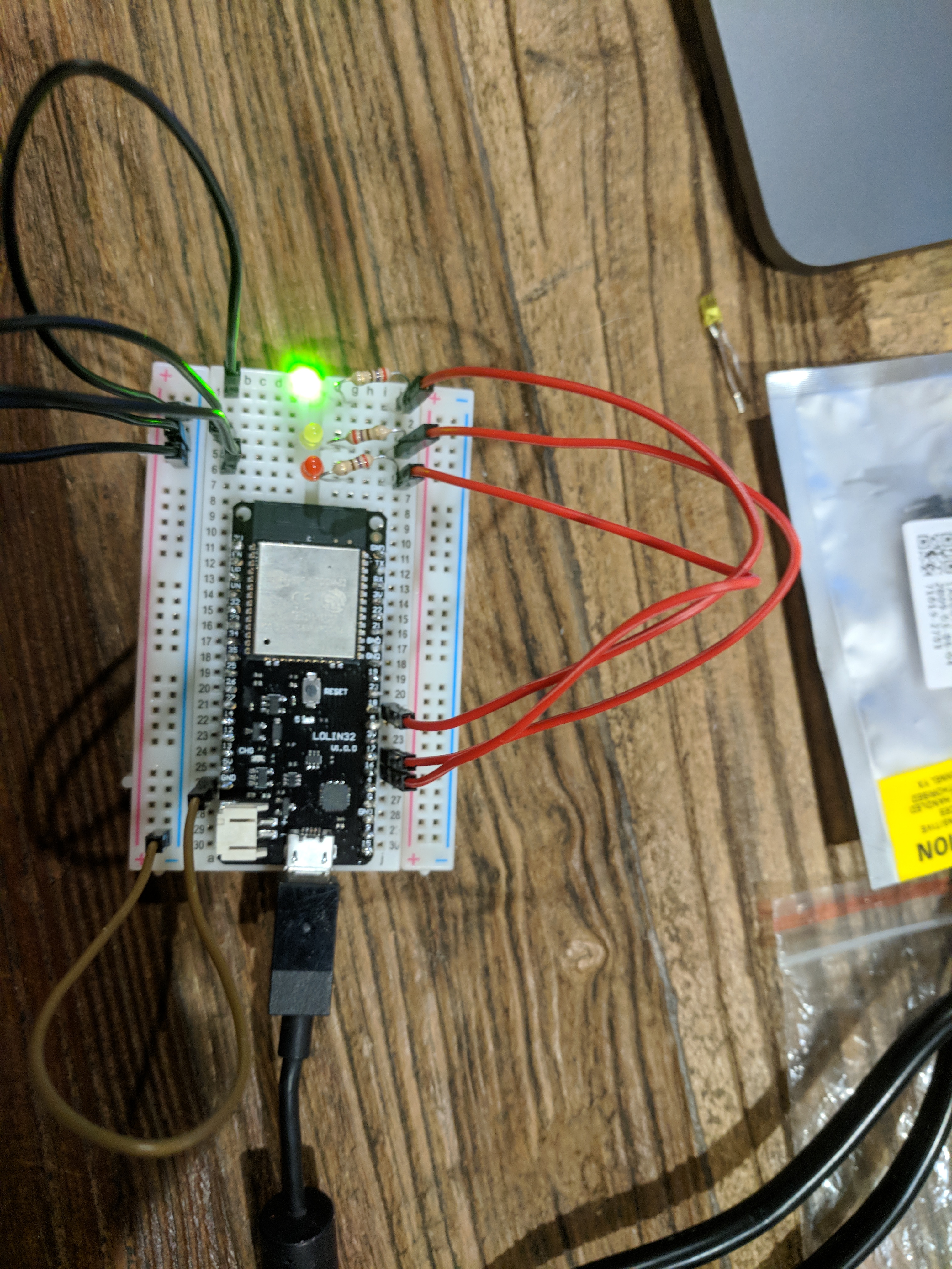
OK, so we can control the GPIO pins on the board (those with numbers) to either turn them on or off (HI or LOW). What I’ve done here is attach a resistor and LED to 3 of the GPIO pins and we’ll have the code cycle through those every second.
I’ve annotated the code with comments, but one important thing to note is that the GPIO pins can work on either input or output, so we have to set the mode to output (we’re outputting voltage to power the LEDs, not reading input data).
#include <stdio.h>
#include "mgos_app.h"
#include "mgos_gpio.h"
#include "mgos_timers.h"

// Define the GPIO pins for the LEDs
#define RED_LED 16
#define YELLOW_LED 17
#define GREEN_LED 18

// Initialise states for LEDs, start with the red on and others off
bool redOn = 1;
bool yellowOn = 0;
bool greenOn = 0;

// This function gets invoked by the timer, every X seconds
static void timer_cb(void *arg) {

  // Check which LED is on, then flip the next one on
  if (redOn){
    redOn = 0;
    yellowOn = 1;
    greenOn = 0;
    printf("YELLOW\n");
  } else if (yellowOn){
    redOn = 0;
    yellowOn = 0;
    greenOn = 1;
    printf("GREEN\n");
  } else if (greenOn){
    redOn = 1;
    yellowOn = 0;
    greenOn = 0;
    printf("RED\n");
  }

// Update states of LEDs /GPIO pins
  mgos_gpio_write(RED_LED, redOn);
  mgos_gpio_write(YELLOW_LED, yellowOn);
  mgos_gpio_write(GREEN_LED, greenOn);

  (void) arg;
}

// Entry point to app
enum mgos_app_init_result mgos_app_init(void) {
  // GPIO pins can work on input or output, as we're lighting LEDs, they
  // are all set to output
  mgos_gpio_set_mode(RED_LED, MGOS_GPIO_MODE_OUTPUT);
  mgos_gpio_set_mode(YELLOW_LED, MGOS_GPIO_MODE_OUTPUT);
  mgos_gpio_set_mode(GREEN_LED, MGOS_GPIO_MODE_OUTPUT);

  // Every 1 second, invoke timer_cb. 2nd arg means repeat continuously
  mgos_set_timer(1000 , 1 , timer_cb, NULL);

  return MGOS_APP_INIT_SUCCESS;
}
Also note that some of pins are reserved, here’s a quote from Kolbans book (well worth checking out if you haven’t already)
There are 34 distinct GPIOs available on the ESP32.
They are identified as:
• GPIO_NUM_0 – GPIO_NUM_19 Page 232
• GPIO_NUM_21 – GPIO_NUM_23
• GPIO_NUM_25 – GPIO_NUM_27
• GPIO_NUM_32 – GPIO_NUM_39
The ones that are omitted are 20, 24, 28, 29, 30 and 31.
Note that GPIO_NUM_34 – GPIO_NUM_39 are input mode only. You can not use these pins for signal output.
Also, pins 6, 7, 8, 9, 10 and 11 are used to interact with the SPI flash chip … you can not use those for other purposes.
Build and deploy the LED blinker code using
mos build && mos flash && mos console
Now we need to hook up the components, but at least with the above running you can use a multimeter to check the pins are being triggered, put the black probe on GND then the red on one of the specified pins, every 3 seconds you should see it powered on for 1 second, we’re almost there!
Prototyping the electronics
The easiest way of connecting this all up is with a breadboard. Take a positive lead from each of the 3 pins, then pass each one through a resistor, the LED, and then back to ground, you’re setting this up in parallel and only one route will be powered at a time.

Remember to have the longer legs on the LED on the positive side, the resistors can be either way around, it doesn’t matter. You can also route all 3 to the same ground, I’ve used the negative rail on the breadboard to make this a bit cleaner.
Conclusion
That’s it, pretty simple, but it’s covered a lot of groundwork, at least in getting the environment setup, deploying an app, plugging in some electronics and testing it out. Next up I’m planning to use the JSN-SR04 sensor, which is a waterproof ultrasonic sensor. I’m already most of the way there using the LED example, should just be a case of reading from an echo pin!
Feel free to comment or catch me on Twitter if this was helpful!